
Jaguar USB Tap: The agony (of hardware bugs) and the ecstacy (of firmware)

Entry posted by dgrubb
1,073 views
Development environment
To start writing code for our STM32F07 series uC via an ST-Link programmer (embedded in a cheap Nucleo board, see previous entries) all we need are a few easy to obtain tools: a C compiler (although Rust is becoming more interesting as an embedded language), a debugger and a tool for handling communication with the uC over the ST-Link. ST provide several options for fully integrated IDEs with varying levels of platform and license support but my personal preference is to avoid all of them. I dislike large IDEs; partially because they absorb system resources and obfuscate underlying details, partially because of my political zealotry and partially because kids today have it too damn easy with their iThings, ghetto-blasters and whatnot. Rather, I shall be using the GCC compiler, the GDB debugger and OpenOCD for programming, all of which are completely open-source, readily available across platforms and are simple to use (IMHO, YMMV). On a Debian-derived Linux distribution, such as Ubuntu or Mint, they're installed with a one-line apt-get invocation:
$ sudo apt-get install gcc-arm-none-eabi gdb-arm-none-eabi openocd
Magic.
As I'm not planning on using an IDE I need to add a few extra targets to my Makefile to perform the programming and debugging functions an IDE would normally integrate:
make # Build the projectmake clean # Delete compiled objectsmake upload # Use OpenOCD to program the target devicemake debug # Open a debugging session with the targetmake run_gdb # Connect to a debugging session
Fail
With a development environment and initialisation code I was ready to start programming! I hooked up the ST-Link to the target uC, double checked all my power connections, and ran make flash. Nothing. OpenOCD's output indicated it was unable to detect a target. However, it did detect the target supply voltage so at least some part was functional. As an experiment I applied a jumper from VDD to one of the uC's GPIO and everything came to life. OpenOCD detected and programmed the target. Curious ...
I programmed the uC a few times with some simple code that just went into loops or incremented variables to ensure that I could connect a GDB debugging session without any further problems. Satisfied, but still confused about the previous behaviour, I tried setting the GPIO as input pins whereupon I lost contact with the uC again. This time, applying power to GPIO failed to revive the board. Confused and frustrated I went back to my original schematic to search for any kind of clue. It was pretty obvious what had happened: I had made a mistake in drawing the schematic symbol for the uC itself, assigning the same number to two different pins.
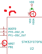
This error percolated all the way down to the trace routing leaving VDDA unconnected. By bridging the GPIO to VDD I had inadvertently provided sufficient power to the GPIO block for the pins to function, that in turn allowed the GPIO pins which double up as a serial programming port to work. By enabling the GPIO pins as inputs I was switching their power source to VDDA. One quick mod to verify this was what was going on ...
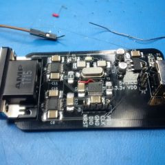
... and I'm going to need to redesign the PCB. Lesson learned, which, frankly, I should have already been cognizant of, is not to rush and take the time to double, triple and quadruple check your design before sending the gerber files off to the PCB manufacturer.
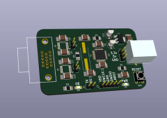
We can rebuild him
As I'm going to have to redesign the PCB anyway I'm going to make a few changes I was thinking about doing anyway:
- Switch from the 20-pin TSSOP uC package to a larger 48-pin LQFP. I really liked the idea of using the smaller package for space efficiency and all the required functions fit nicely into that layout. However, it also meant I had to dedicate the two programming pins to GPIO functions so I can't debug while running all the pins. That won't be much of a problem after I've finished all the code, but for the sake of an easier debugging process it'll be nice to separate those functions.
- Add jumpers to the output enable lines of the logic level translation chips so I can manually control those devices, allowing me to turn them on, off, or let the uC drive them.
- With the larger uC package I can also make use of one of the UART ports for a bit of simple status output without an ST-Link. Could come in handy.
- Add a button to allow for manual control over NRST, so I can reset the uC without powering down the whole device.
We'll get to the Jaguar parts soon. Honest.

0 Comments
Recommended Comments
There are no comments to display.