

mojoatomic
-
Posts
20 -
Joined
-
Last visited
-
Days Won
2
Content Type
Profiles
Forums
Blogs
Gallery
Store
Events
Downloads
Posts posted by mojoatomic
-
-
I have a Light Sixer that has horrendous RF interference. I tried everything I could think of to fix it, but eventually gave up on it.
I wonder if any of this would help it.
Almost certainly. That RF interference is nothing more than ripple current and spikes being amplified and displayed. It's possible your RF cable has seen better days, but it's easy to make one out of modern RG6 cable and compression connectors and have a superior cable in all the ways that are measurable.
-
I love this! Thanks so much for this info. LOVE IT.
You're welcome, hope it's useful to folks :-)
-
On both 6 & 4 switch systems, ripple current plays a very large roll in picture quality and longevity of components. Especially on the 2 input caps, which are .22uf on the 6 switch and .1uf on the 4 switch units. Sometimes seen in pairs, sometimes not, based on the rev level of the board - we'll get to that :-)
Further, electrolytic caps degrade from spec after about 10 years - weather they're in service or not. Electrolytic caps have a shelf life, and that big fat 2200uf filter cap can cause some nasty issues with your picture for sure. That little .47uf cap will put a snowstorm and bright spots on the screen as well.
Recently, I've seen MANY folks converting to composite on these systems, with mixed results. Not all AV kits are created equally and some are better than others, but simply shotgunning one of these kits into a 2600 is unlikely to solve the underlying issues the unit has. It's a garbage in, garbage out principal.
Simply changing from RF to composite won't do you much good if your still amplifying line noise and ripple by pushing a signal through failed caps.
Besides that, a properly adjusted 2600 with a good RF cable can be crystal clear. I'm more of a purist, but that's just me. The same principal and outcome will hold true for RF or composite.
There's another issue, and it relates to the filter or "snubber caps" as they're sometimes referred to. Here's the real deal - they're sacrificial. They're purpose is to take the hit and protect the voltage regulator, 2200uf filter cap and the 9v unregulated reference downstream (on the 4 switch models). As they take hits over the years, they break down and ripple current begins to bleed through - breaking down the 7805 5v voltage regulator.
On a final note, Atari was cheap, but unpredictable. They cut corners in some places (removing components) and adding strange ones (aluminum shielding on the 4 switch switches during service and later factory installed).
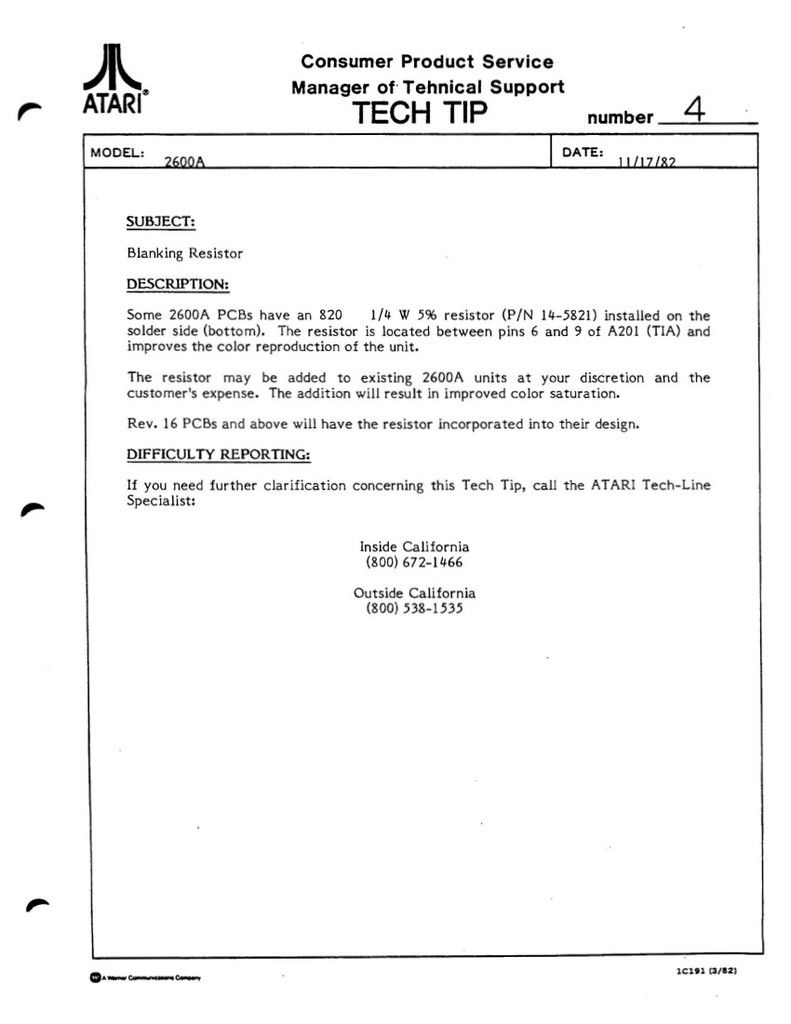
One of the price cutting measures they took was to remove a blanking resistor from all 4 switch models up to version 16 on the boards. This resistor had existed as an 680ohm part strung between pins 6 & 9 of the TIA chip and added those eye popping colors we love so much. In 1982, Atari released a service bulletin "Tech Tip 4" that gave service guys the option of adding this resistor back as an optional billable part during service. In practice, we just added it anyway because the cost was negligible and we were in there anyway, and it makes a HUGE improvement to the picture quality on 4 switch units. The tech tip specified an 820ohm resistor was to be used, soldered between pins 6 & 9 of the TIA on the underside of the board.
The last high failure point is the power jack - they should have used Switchcraft jacks, they were making them at the time, but they cost a bit more.
Here's how to fix all of it.
On the Heavy sixer
Switchboard:
Replace C103 & C104 with a .22uf 100v or better mylar cap - regardless of what you find there.
Replace C106 with a 2200uf 16v or higher electrolytic cap
Replace A101 with a 7805 Voltage Regulator
Replace C105 with a 4.7uf 35v or higher electrolytic cap
Mainboard:
Replace C201 with a 4.7uf 35v or higher electrolytic cap
Replace J201 with a Switchcraft jack
On the Light Sixer
Switchboard:
Replace C103 with a .22uf 100v or better mylar cap - regardless of what you find there.
Replace C106 with a 2200uf 16v or higher electrolytic cap
Replace A101 with a 7805 Voltage Regulator
Replace C105 with a 4.7uf 35v or higher electrolytic cap
Mainboard:
Replace C201 with a 4.7uf 35v or higher electrolytic cap
Replace J201 with the Switchcraft jack
4 switch units - both woody and Vader variants rev 1-16
Replace C241 & 242 with a .1uf 100v or better mylar cap - regardless of what you find there. Versions 8's will almost always have ceramic disk... replace them with mylar.
Replace C243 with a 2200uf 16v or higher electrolytic cap
Replace A203 with a 7805 Voltage Regulator
Replace C201 & C214 with a 4.7uf 35v or higher electrolytic cap
Replace J201 with a Switchcraft jack
IF you have a 4 switch unit AND your board revision level is LESS THAN version 16, install the 820ohm resistor between pins 6 & 9 of the TIA chip on the SOLDER SIDE of the circuit board.
Other things to do while your in there...
On 6 switch units:
reflow solder on the cables connecting the swithboard and motherboard. The flex and move every time the unit is moved.
All units:
Have a look at all of solder points on the 3 big IC's (CPU, TIA & RIOT) and reflow the joints if you need to. Pro tip - almost ALL TIA chips need a reflow - cold or cracked joints here will give you a very ratty picture, even if the unit is functioning.
Flow new solder on the connector for the RF unit. (3 or 5 pin)
Reflow ALL pins on the joystick ports and switches.
Disassemble and clean or use contact cleaner on all switches. There were 2 types of switches used for channel select and difficulty - one is easy to take apart and clean... the other you're better off just replacing it.
Unless you have a need to - I.E. no sound... STAY AWAY from the 2 polystyrene sound caps @ C206 & C207 - they are devilishly hard to solder without damaging them if you don't know your you're doing, and unless you use temp control on your iron and a clipable heat sink on the upper leads of the caps.
In order of failure - RIOT, TIA and then CPU - just speaking from my experience here, YMMV
Image below shows where to solder the 820ohm resistor on 4 switch boards.
I've posted SOME of this recently elsewhere, but I hope some folks here can make use of it -


- Atari 5200 Guy, HDN and RickR
-
 3
3
-
Welcome to the good ship Atari I.O, mojoatomic

I can see yours is a Skill Set a lot of folks are going to appreciate.
Thanks for being part of the community here.
Thanks for the welcome!
-
Welcome, hope it helps
The way this repair came about was, I got tired of replacing these things because it takes a good bit to get them heated up and off, and, it's wasteful. Besides... we had these new hires always rotating through the shop,,,
so I'd get them to pull the RF section off the boards where they had tested bad and then had them disassemble them. It was just really good practice for them to learn proper soldering/desoldering technique, plus I could show them how to set up a scope to verify proper operation of the RF section after they had reinstalled them. The other added benefit to them was I made sure that they got recorded credit for that portion of the repair, and they learned how to fill out the NARDA paperwork so we could get reimbursed.
-
Welcome aboard!
Thanks!
-
I got this fellow for Christmas ... https://www.amazon.com/Aoyue-Contained-Desoldering-Internal-Carrying/dp/B00PGFAJWS/ref=sr_1_1?s=hi&ie=UTF8&qid=1488422825&sr=1-1&keywords=aoyue+8800
first thing I used it on was the hex buffer chip on a heavy sixer. I was putting off doing it for a very long time cause of damage I did to other cadavers I was working on.
I was getting pretty good at using the bulb iron. https://www.radioshack.com/products/radioshack-45-watt-desoldering-iron?gclid=CPeHkebnttICFQZYDQodUwMH4g
but the vacuum pump was a real pleasure to use. I am still unsure how the manufacturers name is pronounced

welcome to the site
Wondered how you did without it for so long didn't you? :-)
It really is the only way to preserve these boards for the future - the desoldering vacuum pump guns don't lift pads and you only keep heat on the board for a brief period of time. Best to flow fresh solder into the joints beforehand, though - makes the joint let go much more easily.
- Lost Dragon and chas10e
-
2
-
Welcome!
Nice to have someone with your background around these here parts!
Thank you, like your videos BTW.
- Lost Dragon and nosweargamer
-
2
-
Welcome mojo! Hope you stick around and have a great time. We have a great community!
Thanks!
-
Welcome to the forums mojoatomic! Great to have you here!!
Thank you!
- Rowsdower70 and Lost Dragon
-
2
-
Quick tip to save you a few clams...
Everyone says these are unrepeatable - well... send me all you have, I can use them :-)
OK, after you remove the RF unit from the board, have a look at the inside - not much to it. Certainly no magic -
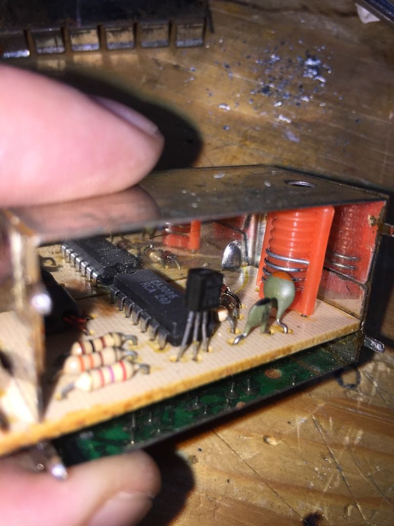
Have a look where the perfboard joins the case... see the solder pads and joints? Remove as much solder from the 2 joints on the side as you can, and then use desoldering braid for the rest - after that, just pull the board out.. like so -
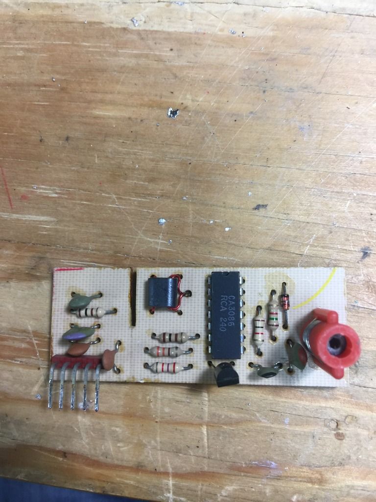 Make a few tests - it's a bad IC this time, just a transistor array. DON'T install an IC socket for this repair... solder the array directly to the board. These chips are cheap... line .39 cents or so. The transistor is like .07 cents. There's NOTHING else to go bad here :-)
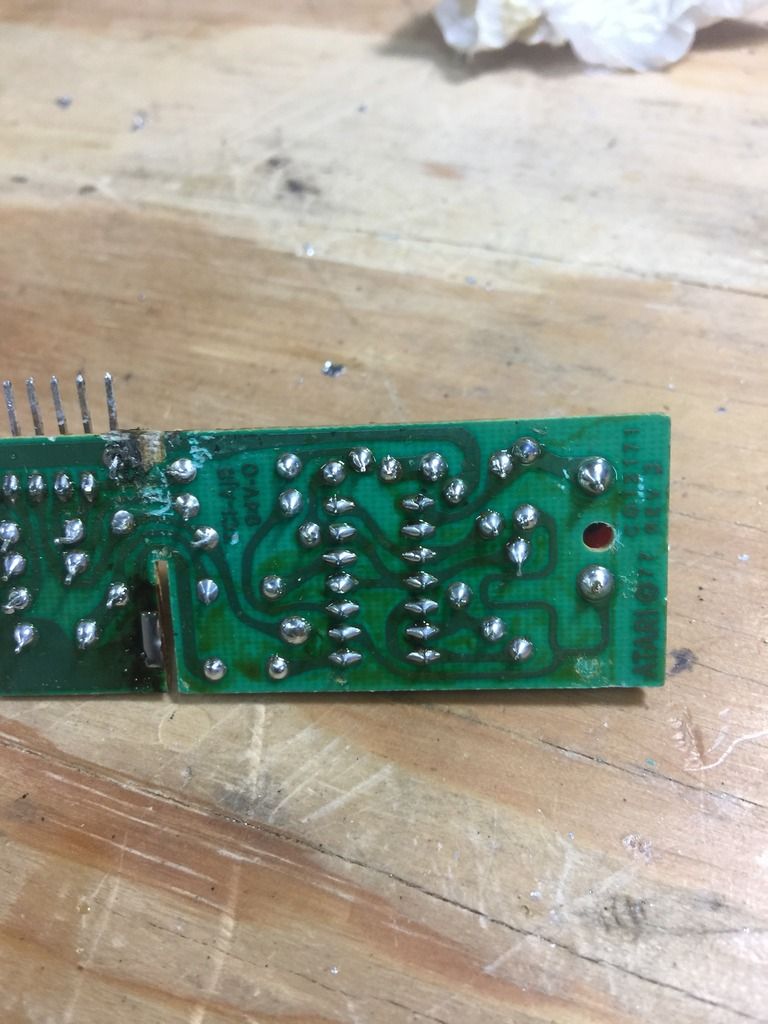
Nice, shiny and new. Button it back up and reinstall.
- jmjustin6, RickR, Rowsdower70 and 2 others
-
5
-
Wow great to have you here. I know you could help out people here with your knowledge
Thanks for the welcome!
- Justin, Lost Dragon and DCG
-
3
-
Welcome yo!!!!! Always amazing to have knowledgeable techs here. I know I might pick your brain from time to time.
Thanks! Happy to help however I can -
- Justin, Lost Dragon, Rowsdower70 and 1 other
-
4
-
Welcome to Atari.io!
Thanks!
- Justin, Rowsdower70, Lost Dragon and 1 other
-
4
-
I've got a nice little project to work on. A 2600 4 switch board that needs one of the joystick ports replaced. I've got a new port. But not the confidence to de-solder and remove the old part.
What do you use as a de-solder tool? I've got both copper braid, and one of those clicky thumb sucker tools (it's never been opened -- never used it). No rush or anything, I was just curious which would be the better bet. My plan was just to try both and see with works best. After all, there are 9 pins to experiment on.

Well, I like most things Hakko and have for years, but when you buy it... you'll know it. My wife got me one of these 2 weeks ago for my birthday - and I LOVE it. I've had the Hakko version for awhile, but wanted another one wasn't prepared to drop another $1200 on another Hakko.
I'd put the desoldering braid up, it's just gonna lift the pads and make you mad. I'd use the manual pump for sure. Just make sure to flow fresh solder (60/40 tin/lead) into the joint first, then use the pump.
- Lost Dragon, RickR, Justin and 2 others
-
5
-
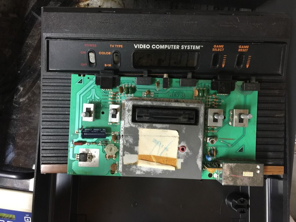
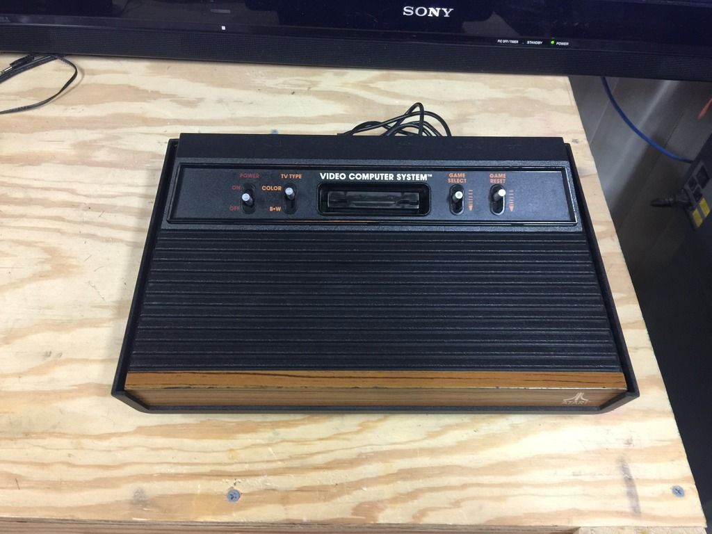
4 switch unit - before and after complete refurb and application of factory modifications - (service bulletin tech tip 4) - yes, that's RF :-)
First video is after refurb but before adding an 820ohm resistor across TIA pin 6 & 9, second video is after.
-
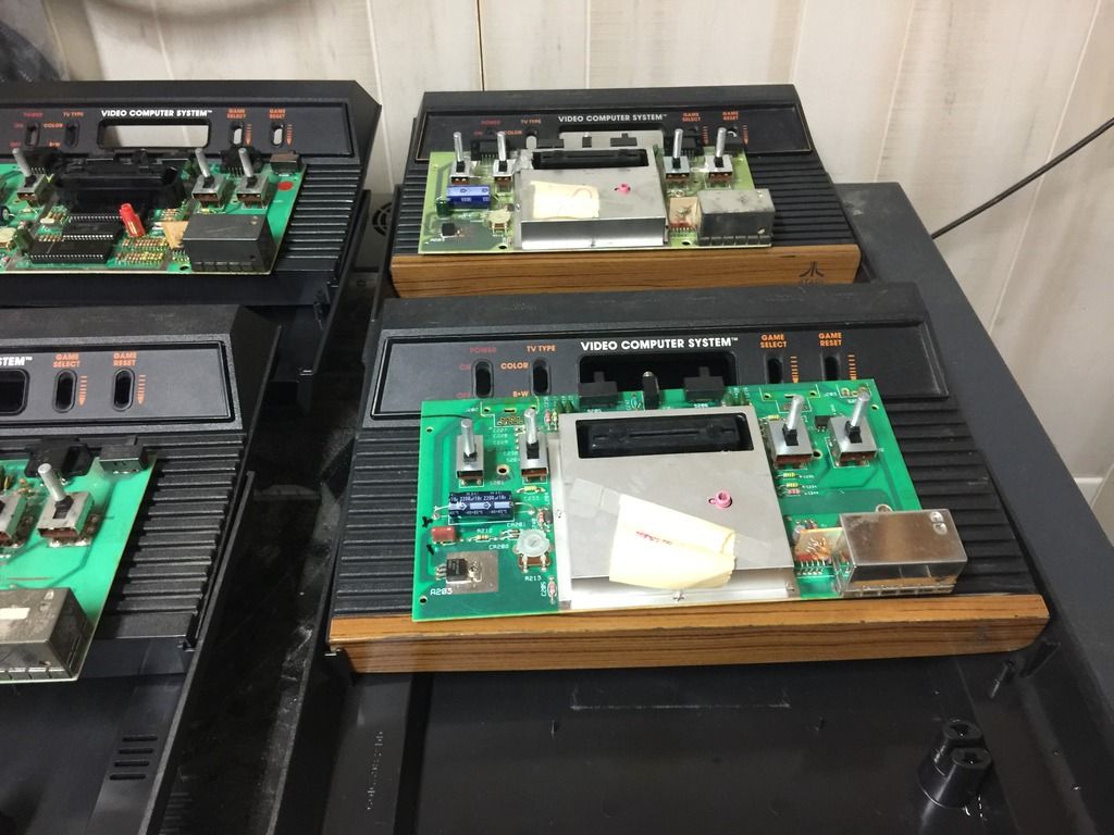
These have been posted elsewhere, but just came off the bench...
Everything washed and polishedTop left - caps, voltage regulator and replaced female cart connector (too far gone to be reliably repaired). Original symptom was blank screen, issue was RIOT, replaced. After that it didn't like Activision, so cart connector replaced with new OEM connector. Replaced jack. It's ready for another 30 years now.Bottom left - caps, voltage regulator good, replaced left joystick port, reflowed dry IC joints, replaced jack made RF adjustment. This is a version 8 board - my favorite of all the 4 switch units.Top right - caps, voltage regulator, TIA showed bad on burn in after 10 minutes (wavy rainbows, then blank) so... I replaced it. Replaced channel switch, reflowed high stress joints and all IC joints. Replaced jack.Bottom right - caps, voltage regulator, both joystick ports, reflowed switches and IC joints, replaced jack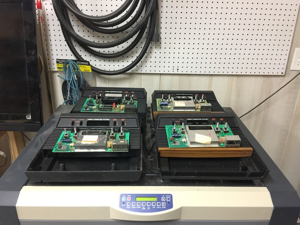

- Justin and Sabertooth
-
2
-
Thanks for the welcome! Hope I can add to the discussions and be of use to folks.
- Rowsdower70, DCG, Justin and 1 other
-
4
-
- Popular Post
- Popular Post
Hi all, found this forum, read a few posts and had to join. This is only the second Atari forum I've participated in
last ones were BBS's, so it's been awhile I started out in the early days as an Atari authorized service center tech and repaired/refurbished more consoles than you could shake a stick at. Looks like Atari never left and I've still played it all of these years.
I'm an IT admin now, but I started out as a lowly bench tech. If you were good, they called you a "gunslinger" back then - which seems kind of silly, but it was considered high praise at the time. It was a name reserved for the high end guys who took care of the issues no body else had any luck with, or the ones that were considered to difficult for field personal. Not necessarily related to Atari, just in general.
We took contracts with any manufacturer who needed depot style repair where we could get decent money and secure a steady parts chain and factory level service material. I've professionally repaired everything from Bang & Olufsen, Macintosh (not the computer), Apple (the computer), Commodore, Nakamichi, Data South, Unisys, Daisy Tech, Atari (many models), Marantz and more. Nothing was thrown away back then - if it was of quality & had value, it was all repaired. The Atari was no exception - the 2600's were extremely well made units, and made to be repaired. Actually... they were made to be repaired by folks who knew how to use o-scopes and logic probes. The manuals are geared to flow chart troubleshooting , but the real repair happened at the end of a scope probe. The flow charts were for the new guys and ones destined for field repair.
Anyway, a friend asked me to do a repair on a 2600, so I got into the loft looking for a few parts and would up finding all of my service gear, parts and manuals that I had packed away for who knows why (but I'm glad I did) - and it turns out... I can still repair them like nobody's business.
- Atari Creep, Arenafoot, greenween and 7 others
-
10


FS: Sears H6ers, Atari L6er, CX-10, Sears Heavy paddles, CX78
in For Sale
Posted
I'd like the light sixer!